 English
 عربى
عربى
News
Home / News / Industry News / Industrial Membrane Guide: Types, How They Work, and How to Choose the Right One
Content
An industrial membrane is a semi-permeable barrier that separates components of a liquid or gas stream based on differences in particle size, molecular weight, ionic charge, or chemical affinity — without requiring heat, chemical reactions, or phase changes. The driving force is almost always a pressure differential between the feed side and the permeate side of the membrane, which pushes the target species through the membrane while retaining unwanted components on the feed side. The two output streams — permeate (what passes through) and retentate (what is held back) — are each collected and used or disposed of according to the process design.
This separation mechanism makes industrial membrane filtration fundamentally different from conventional depth filtration or chemical precipitation. Depth filters — such as sand filters or bag filters — trap particles throughout the filter medium and must be periodically replaced or backwashed. Chemical precipitation changes the composition of the stream and introduces reagent residuals that must be managed downstream. Industrial membranes separate cleanly based on a fixed physical threshold, produce no chemical by-products, and can be cleaned and returned to service without replacement in most operating scenarios. These characteristics explain why membrane technology has expanded from its original applications in water desalination and dairy processing into virtually every industry where fluid separation or purification is required.
The most important practical distinction in industrial membrane systems is between dead-end filtration and cross-flow filtration. In dead-end mode, all of the feed fluid flows perpendicularly through the membrane until the retained material blocks further flow. This is suitable for clean-liquid polishing with low solids loading. In cross-flow (or tangential flow) filtration — which dominates industrial membrane applications — the feed flows parallel to the membrane surface at high velocity, continuously sweeping retained material away and preventing the buildup of a filter cake that would otherwise block flow. Cross-flow operation is the reason industrial membranes can run continuously on high-solids feeds without constant replacement.
Industrial membrane filtration is divided into four categories based on the pore size range of the membrane and the corresponding molecular weight or particle size cutoff. Each category addresses a different separation problem and operates at different pressures. Selecting the correct filtration type is the first decision in any industrial membrane system design.
Microfiltration membranes have pore sizes in the range of 0.05 to 10 microns (µm) — the coarsest of the four types. They operate at low transmembrane pressures (typically 0.1 to 2 bar) and are used to remove suspended solids, bacteria, yeast cells, and fat globules from liquid streams. Because microfiltration does not retain dissolved molecules — it is entirely a size-based physical separation — it is commonly used as a first-stage pre-treatment before a finer membrane step, or as a clarification and sterilisation stage in food and beverage processes. Typical MF applications include cold sterile filtration of beer and wine, removal of biomass in fermentation processes, clarification of fruit juices, and pre-treatment of wastewater before ultrafiltration or reverse osmosis steps.
Ultrafiltration membranes have pore sizes between 0.01 and 0.1 microns, with molecular weight cutoffs (MWCO) typically ranging from 1,000 to 500,000 Daltons. Operating at transmembrane pressures of 1 to 10 bar, UF retains bacteria, viruses, proteins, starch, and colloidal particles while allowing water, salts, and low-molecular-weight solutes to pass as permeate. This selective retention makes UF the workhorse of industrial membrane processing across a wide range of sectors: protein concentration and purification in dairy and pharmaceutical manufacturing, macromolecular fractionation in biotechnology, removal of colloidal particles and organics in drinking water treatment, and pre-treatment ahead of nanofiltration or reverse osmosis to extend their service life. UF also forms the membrane layer in membrane bioreactors (MBRs) used in wastewater treatment.
Nanofiltration membranes have pore sizes in the approximate range of 1 to 10 nanometres and are designed to remove divalent ions (calcium, magnesium, sulphate), medium-molecular-weight organics, and colour-causing compounds while allowing monovalent salts (sodium chloride) and water to pass. Operating pressures are typically 5 to 20 bar. Nanofiltration is used for water softening (removal of hardness ions), desalination of brackish groundwater where partial salt removal is sufficient, decolouration of sugar solutions, concentration of low-molecular-weight organics in food processing, and treatment of industrial effluents containing organic micropollutants. Its ability to selectively remove divalent ions while passing monovalent ions is a property no other membrane type replicates — making NF the specific choice for water softening applications where full desalination would remove beneficial minerals.
Reverse osmosis membranes have the tightest separation of the four types — with effective pore sizes below 1 nanometre — and reject virtually all dissolved solids, monovalent ions, and organic molecules above approximately 100 Daltons. Operating pressures range from 10 to 80 bar depending on feed salinity, making RO the most energy-intensive membrane filtration type. RO is the standard technology for seawater desalination, production of high-purity process water in semiconductor and pharmaceutical manufacturing, boiler feed water treatment, and concentration of valuable dissolved solids in food, beverage, and chemical processing streams. The retentate from an RO system is a concentrated brine or concentrate stream that requires further management — either disposal, further concentration, or recovery of its dissolved content depending on the application.
| Type | Pore Size | MWCO | Operating Pressure | What It Removes | Typical Application |
|---|---|---|---|---|---|
| Microfiltration (MF) | 0.05 – 10 µm | N/A | 0.1 – 2 bar | Suspended solids, bacteria, yeast, fat | Beverage clarification, fermentation, pre-treatment |
| Ultrafiltration (UF) | 0.01 – 0.1 µm | 1K – 500K Da | 1 – 10 bar | Viruses, proteins, colloids, polymers | Dairy, pharma, wastewater, water treatment |
| Nanofiltration (NF) | 1 – 10 nm | 150 – 1,000 Da | 5 – 20 bar | Divalent ions, organics, colour | Water softening, sugar decolourisation, effluent treatment |
| Reverse Osmosis (RO) | <1 nm | <100 Da | 10 – 80 bar | All dissolved solids, monovalent ions | Desalination, pure water production, concentration |
The physical and chemical performance of an industrial membrane depends critically on the material it is made from. Membrane materials fall into two broad categories — polymeric and ceramic — each with a distinct balance of cost, chemical resistance, mechanical durability, and cleanability. Choosing the wrong material for the feed chemistry or cleaning regime is one of the most common causes of premature membrane failure in industrial systems.
Polymeric membranes dominate the industrial membrane market by volume, primarily because they are less expensive to manufacture, available in a wider range of module configurations, and adequate for the large majority of process streams encountered in water treatment, food and beverage, and general industrial applications. The most commonly used polymers each have specific performance characteristics:
Ceramic industrial membranes are manufactured from inorganic oxide materials — most commonly aluminium oxide (alumina, Al₂O₃), titanium dioxide (titania, TiO₂), or zirconium oxide (zirconia, ZrO₂) — often in multilayer configurations where a coarse support layer provides mechanical strength and a thin, finely porous top layer provides the actual separation. Ceramic membranes cost significantly more than polymeric alternatives of equivalent area — typically five to twenty times more per square metre — but they offer a set of performance advantages that justify this premium in demanding applications:
The membrane material and filtration type define what a membrane can separate. The module configuration — how the membrane is physically arranged within its housing — determines how efficiently it operates at process scale, how it handles suspended solids, and what it costs per unit of treated throughput. Selecting the wrong module configuration for a feed stream leads to accelerated fouling, high cleaning frequency, and short element life.
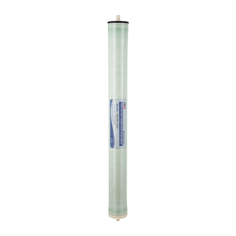
Spiral wound modules are the most widely used configuration in industrial RO, NF, and UF applications for relatively clean feed streams. The membrane is manufactured as flat sheets, assembled with feed and permeate spacers between them, and wound in a spiral around a central perforated permeate collection tube. This geometry provides a very high membrane area per unit volume — a standard 8-inch diameter, 40-inch long element contains 37 to 40 m² of active membrane area — at low manufacturing cost. The limitation of spiral wound modules is their vulnerability to suspended solids: particles accumulating in the narrow feed spacer channels cause rapid pressure drop increases and irreversible fouling. Feed water SDI (Silt Density Index) below 5, and preferably below 3, is required for reliable long-term operation of spiral wound elements, which means adequate pre-treatment is mandatory for most real-world feed sources.
Hollow fiber modules pack thousands of fine, self-supporting membrane tubes — typically 0.5 to 2 mm internal diameter — into a bundle inside a pressure vessel. The extremely high packing density is the key advantage: a 0.04 m³ membrane vessel can house 575 m² of 90 µm-diameter hollow fibers, compared to approximately 30 m² of spiral-wound flat sheet membranes in the same volume. Hollow fiber modules dominate in large-scale UF and MF applications for water treatment and wastewater reuse, where their ability to be backwashed periodically to remove accumulated solids on the outside of the fibers enables economical operation on turbid feed streams without continuous cross-flow. The principal limitation is moderate tolerance of suspended solids in the feed — very high TSS or fibrous materials can block the fiber bundle and resist backwashing.
Tubular membranes consist of individual membrane tubes with internal diameters of 5 to 25 mm, each contained within a supporting outer jacket, connected in series within the housing. The large internal diameter allows high feed velocity through the tube, which generates significant turbulence and shear at the membrane surface — making tubular modules the most fouling-tolerant configuration for high-suspended-solids or viscous feeds. They are widely used in dairy processing (whole milk, cream concentration), juice processing, pigment recovery, and industrial wastewater treatment where spiral wound or hollow fiber modules would foul immediately. The trade-off is cost: membrane area per unit volume is much lower than hollow fiber or spiral wound designs, making tubular systems more expensive per unit of permeate produced. Pre-treatment requirements are minimal, which partially offsets this disadvantage in difficult feed applications.
Plate and frame modules stack flat membrane sheets between plates, similar in concept to a filter press. They are less common in high-volume industrial applications due to their higher cost and lower packing density, but they offer easy disassembly for membrane inspection and replacement — an advantage in applications where membrane life is short or where visual inspection of fouling is valuable for process optimisation. Plate and frame configurations are also used in electrodialysis and certain specialty gas separation applications where the flat sheet format is required by the process chemistry.
| Module Type | Packing Density | Feed TSS Tolerance | Cleanability | Best Application |
|---|---|---|---|---|
| Spiral Wound | High | Low (SDI < 5) | CIP only | RO/NF/UF on pre-treated feeds |
| Hollow Fiber | Very High | Medium | Backwash + CIP | Large-scale UF/MF, water treatment |
| Tubular | Low | Very High | High-velocity flush + CIP | Dairy, juice, high-viscosity or high-solids feeds |
| Plate and Frame | Low | Medium | Easy physical access | Specialty separation, electrodialysis |
Industrial membrane systems now operate across a remarkably broad range of sectors and process types. The following covers the most significant application areas and the specific membrane types used in each.
Water treatment is the largest single market for industrial membranes. MF and UF membranes are used in drinking water production to remove turbidity, bacteria, and Giardia/Cryptosporidium cysts with a physical barrier that does not rely on chemical dosing for its efficacy. NF and RO are used for groundwater softening, brackish water desalination, and seawater desalination. In industrial wastewater treatment, membrane bioreactors (MBRs) combine biological degradation of organic pollutants with UF membrane separation of the treated effluent, producing a consistently high-quality permeate suitable for direct reuse without further treatment. MBR systems are now routinely used in textiles, food processing, paper, and chemical wastewater applications where effluent reuse or zero liquid discharge goals require superior quality output compared to conventional activated sludge processes.
The dairy industry was one of the first sectors to adopt industrial membrane technology at large scale, and membranes remain central to dairy processing. UF membranes concentrate milk proteins for cheese production, standardise the protein content of liquid milk, and recover whey proteins from whey streams — a high-value separation that converts a former waste stream into a premium nutritional ingredient. MF membranes clarify and cold-sterilise liquid dairy streams without heat treatment, preserving flavour and nutritional quality. In the broader food industry, UF concentrates juice proteins and enzymes; NF concentrates sugar syrups and removes colour; and RO concentrates liquid food streams for transportation or further processing at reduced energy cost compared to evaporation.
Industrial membrane separation in pharmaceutical and biotech manufacturing serves two primary functions: purification (removing impurities from a target molecule) and concentration (increasing the target molecule's concentration in the final product). UF with defined MWCO values is used to retain target proteins, enzymes, monoclonal antibodies, and virus particles while removing smaller impurities and buffer salts in a process called diafiltration — essentially a continuous washing of the retained macromolecule with fresh buffer. Membrane sterile filtration using 0.22 µm MF membranes removes all bacteria and spores from final drug products or bioprocess streams as an alternative to heat sterilisation. Ceramic membranes with full steam-sterilisability are preferred in applications where the same membrane surface must be validated for repeated sterile processing cycles.
Industrial membrane separation is increasingly used in chemical manufacturing to reduce energy consumption compared to thermal separation methods such as distillation and evaporation. Solvent-resistant nanofiltration (SRNF) membranes operate in organic solvent streams to concentrate catalysts, recover expensive reagents, or separate reaction products from unreacted starting materials. In the oil and gas sector, gas separation membranes — a distinct category from liquid-phase membranes — separate CO₂ from natural gas, recover hydrogen from refinery streams, and remove water vapour from process gas. Membrane-based solvent recovery in pharmaceutical synthesis is a growing application area as the industry reduces solvent consumption and waste generation.
Semiconductor chip and LCD panel manufacturing requires ultrapure water with extremely low levels of particles, bacteria, dissolved organics, and ionic contaminants. Industrial membrane systems — typically a sequence of pre-treatment, RO, and electrodeionisation (EDI) or ion exchange polishing — produce the 18 MΩ·cm resistivity water that semiconductor fabrication lines require. MF membranes with very tight particle size ratings (0.05 µm or below) are used at the point of use to prevent particle contamination of process baths and rinse water at the nanometre scale of modern chip features.
Fouling — the accumulation of unwanted material on the membrane surface or within its pores — is the central operational challenge in every industrial membrane system. It reduces permeate flow, increases transmembrane pressure, decreases separation selectivity, and ultimately shortens membrane element life. Understanding fouling mechanisms and how to prevent or manage them is as important as the initial membrane selection.
The following performance changes signal that fouling has developed to the point where cleaning action is required. Waiting longer than these thresholds before initiating cleaning increases the risk of irreversible fouling that cleaning cannot reverse:
Clean-in-Place (CIP) is the standard method for restoring fouled industrial membranes to near-original performance without removing them from the system. A well-executed CIP protocol uses recirculating cleaning solutions at controlled temperature, flow rate, and pH to dissolve, disperse, or kill the fouling material on the membrane surface. Selecting the wrong cleaning chemical for the foulant type is the most common reason CIP fails to restore performance and can also cause irreversible membrane damage.
| Foulant Type | Cleaning Chemistry | Typical pH Range | Notes |
|---|---|---|---|
| Calcium carbonate / sulphate scale | Citric acid, hydrochloric acid (dilute) | 2 – 4 | Do not exceed 4% HCl; confirm membrane acid tolerance |
| Silica scale | Sodium hydroxide (NaOH) | 11 – 12 | Hot caustic (35–45°C) is most effective; requires good rinsing |
| Organic and humic fouling | Sodium hydroxide ± surfactant | 11 – 13 | Higher pH and longer soak time improves organic dissolution |
| Biofouling / biofilm | Alkaline cleaner + biocide (DBNPA or CMIT/MIT) | 11 – 12 | Enzyme-based cleaners for mature biofilms; biocide must be membrane-compatible |
| Protein fouling (dairy/pharma) | Alkaline (NaOH) followed by acid (citric or phosphoric) | 11–13 then 2–4 | Alkaline step denatures protein; acid step removes mineral co-deposits |
| Oil / fat fouling | Alkaline + non-ionic surfactant | 10 – 12 | Higher temperature (40–50°C) significantly improves oil removal efficacy |
The standard CIP sequence for mixed organic and mineral fouling — which is the most common real-world scenario — is to start with alkaline cleaning to address organic and biological fouling first, then follow with acid cleaning to dissolve mineral deposits. Reversing the order (acid first) risks fixing organic fouling onto the membrane surface by denaturing proteins before they can be removed. After each CIP step, thorough flushing to a neutral pH before the next step is essential to prevent chemical reactions between incompatible cleaning solutions in the membrane module. Temperature during CIP should be maintained within the manufacturer's specified limits — typically 35 to 45°C for most polymeric membranes — as higher temperatures increase chemical reaction rates and cleaning effectiveness but risk exceeding the membrane's thermal tolerance.
Industrial membrane selection involves matching multiple system requirements simultaneously — filtration type, material compatibility, module configuration, operating conditions, and total cost of ownership — rather than optimising any single parameter in isolation. Working through these decision points systematically prevents the most common selection errors.
