 English
 عربى
عربى
News
Home / News / Industry News / Reverse Osmosis Membrane: What It Does, How Long It Lasts, and When to Replace It
Content
The reverse osmosis membrane is the central filtering element in any RO water treatment system — it's the component that does the actual separation of contaminants from water. Understanding what it does, and what it doesn't do, helps you make better decisions about system selection, maintenance, and troubleshooting.
A reverse osmosis membrane is a semi-permeable barrier made from a thin polymer film, most commonly thin-film composite (TFC) polyamide. Water is pushed through this membrane under pressure, and the extremely fine pore structure — typically 0.0001 microns in diameter — allows water molecules to pass through while blocking dissolved salts, heavy metals, organic compounds, bacteria, viruses, nitrates, fluoride, chloramines, and a broad range of other contaminants. The filtered water that passes through is called the permeate or product water; the concentrated stream of rejected contaminants that is flushed away is called the concentrate or brine.
To put the filtration precision in perspective: a human hair is roughly 75 microns in diameter, a bacteria cell is around 1 micron, and a reverse osmosis membrane operates at 0.0001 microns — about 750,000 times finer than a hair. This is why RO membranes are capable of removing contaminants that no other filtration method in a residential system can touch, including dissolved ionic compounds that even the best carbon block filters leave behind.
It's important to understand that the RO membrane works as part of a multi-stage system. Pre-filters — typically a sediment filter and one or more carbon filters — remove chlorine, sediment, and organics before the water reaches the membrane. This pre-treatment is not optional; chlorine in particular rapidly degrades polyamide membrane material, and sediment physically blocks and abrades the membrane surface. The membrane cannot perform correctly if the pre-filtration stages are neglected or overdue for replacement.
Most residential and light commercial RO membranes share the same physical format: the spiral wound element. Understanding this construction explains both why RO membranes are effective and why they fail in predictable ways.
A spiral wound RO membrane element consists of multiple flat membrane sheets, permeate spacer mesh, and feed channel spacer mesh rolled tightly around a central perforated product water tube. Feed water enters from one end and flows along the feed channels between membrane layers. Water molecules permeate through the membrane and spiral inward through the permeate spacer toward the central collection tube, which carries the product water out of the element. Concentrated brine exits from the opposite end of the element. This design packs an enormous membrane surface area — typically 1–2 square meters for a standard residential 75 GPD element — into a compact cylindrical housing, making it highly space-efficient.
The functional heart of a modern RO membrane is the thin-film composite (TFC) structure, which consists of three layers bonded together. The outermost layer is an ultra-thin polyamide active layer, typically 0.05–0.2 microns thick, which provides the actual separation selectivity. This sits on a polysulfone microporous support layer approximately 40 microns thick, which provides mechanical stability without impeding water flow. The polysulfone layer in turn sits on a polyester non-woven backing fabric that gives the membrane overall structural rigidity. This three-layer structure allows the active polyamide layer to be made extremely thin — maximizing water flux — while being supported against the hydraulic pressure applied during filtration.
While thin-film composite spiral wound membranes dominate the residential and light commercial market, several membrane types and configurations exist across the broader water treatment industry. Knowing the differences matters when selecting or upgrading a system.
| Membrane Type | Material | Chlorine Tolerance | Rejection Rate | Primary Use |
| Thin-Film Composite (TFC/TFM) | Polyamide | Very Low (<0.1 ppm) | 95–99% | Residential, commercial, industrial |
| Cellulose Acetate (CA) | Cellulose Acetate | Moderate (0.5–1 ppm) | 85–95% | Legacy systems, chlorinated supplies |
| Brackish Water TFC | Polyamide (modified) | Very Low | 97–99.5% | High TDS well water, brackish sources |
| Seawater TFC (SWRO) | Polyamide (high-rejection) | Very Low | 99–99.8% | Seawater desalination |
| Low-Pressure / High-Flux TFC | Polyamide (optimized) | Very Low | 94–98% | Low-pressure residential tankless RO |
For the vast majority of homeowners with municipal water supplies, a standard TFC membrane is the correct choice. Cellulose acetate membranes were more common before the 1990s and are now largely obsolete in new installations, though replacements are still manufactured for legacy systems. If you're drawing from a private well with high total dissolved solids (TDS) above 1,000 ppm, a brackish water membrane may be more appropriate — verify with a water test before selecting.
RO membrane specifications can look overwhelming at first glance, but a handful of numbers matter most for practical selection and performance evaluation. Understanding these specifications helps you compare products accurately and diagnose performance problems when they arise.
Flow rate is expressed in gallons per day (GPD) or liters per day (LPD) and represents how much product water the membrane produces under standardized test conditions — typically 77°F (25°C) water temperature, 60–65 PSI (414–448 kPa) feed pressure, and a specified TDS level (usually 250–500 ppm NaCl). Residential membranes are commonly rated at 50, 75, 100, or 150 GPD. It's critical to understand that these are laboratory test conditions. In practice, colder water or lower pressure will significantly reduce actual output — cold water at 50°F (10°C) may produce only 50–60% of the rated GPD compared to output at 77°F.
Salt rejection rate — typically expressed as a percentage — indicates the proportion of dissolved solids the membrane removes under test conditions. A membrane rated at 97% rejection with 500 ppm feed water will produce permeate at approximately 15 ppm TDS. Premium membranes achieve 98–99% rejection rates. As a membrane ages or becomes fouled, its rejection rate decreases — meaning more dissolved contaminants pass through into the product water. Monitoring TDS before and after the membrane is the most direct way to track rejection performance over time.
Recovery rate describes what percentage of the feed water becomes usable product water versus brine waste. Standard residential RO systems have recovery rates of 15–25%, meaning three to five gallons of water are sent to drain for every gallon of product water produced. Higher-efficiency systems — including permeate pump systems and zero-waste (closed-loop) RO designs — can achieve recovery rates of 50% or higher. The recovery rate is partly a function of membrane design and partly a function of system design; a membrane alone cannot change recovery rate without corresponding changes to brine flow control components.
RO membranes have minimum and maximum operating pressure specifications. Residential membranes typically require a minimum of 40–50 PSI to produce useful flow and are rated for a maximum of 80–100 PSI. Feed water pressure below the minimum results in drastically reduced output and can allow more contaminants to pass through. Pressure above the maximum risks physical damage to the membrane element and housing. If your home water pressure falls below 40 PSI — common in rural areas or upper floors of apartment buildings — a booster pump is needed upstream of the membrane.
A properly maintained TFC reverse osmosis membrane typically lasts two to five years in a residential application. The wide range reflects the significant influence of water quality, pre-filter maintenance, and operating conditions on membrane longevity. Understanding what shortens or extends membrane life helps you manage replacement costs and get the most from your investment.
Factors that extend membrane life:
Factors that shorten membrane life:
Unlike pre-filters, which should be replaced on a calendar schedule regardless of appearance, RO membrane replacement is best triggered by performance monitoring rather than time alone. A membrane that has been perfectly maintained can last five years; one that has suffered chlorine exposure may fail within one. These are the clearest indicators that replacement is due:
Replacing a reverse osmosis membrane is a straightforward DIY task for most residential systems. The process takes about 15–30 minutes and requires no special tools beyond what's typically included with the system. Here's how to do it correctly:
Fouling — the accumulation of unwanted material on or within the membrane — is the primary mechanism by which RO membranes lose performance before the end of their chemical lifespan. Understanding the main fouling types helps you identify the root cause of performance decline and determine whether cleaning or replacement is the appropriate response.
Scaling occurs when sparingly soluble salts — most commonly calcium carbonate (CaCO₃), calcium sulfate (CaSO₄), barium sulfate (BaSO₄), and silica — concentrate on the membrane surface and precipitate as solid deposits. Scaling reduces flux (water production rate) but often leaves rejection relatively intact until the scale becomes severe. Mild scaling can sometimes be addressed by cleaning with a low-pH acid solution (citric acid is commonly used for residential systems) to dissolve carbonate-based scale. Prevention involves maintaining the system's concentration factor within the membrane's specified limits and, for hard water supplies, considering upstream water softening or antiscalant treatment.
Colloidal fouling involves fine particles — clay, silt, iron colloids, organic matter — that deposit on and within the feed channel spacers and membrane surface. This type of fouling causes gradual flux decline and can significantly increase the differential pressure across the membrane element. It is primarily a pre-treatment problem; if the sediment pre-filter is correctly sized and replaced on schedule, colloidal fouling of the RO membrane should be minimal. A high-quality 5-micron sediment pre-filter followed by a 1-micron filter provides substantially better protection than a single-stage pre-filter alone.
Biofouling occurs when bacteria colonize the membrane surface and feed spacer, forming a biofilm layer that physically blocks water passage and can chemically damage the membrane through metabolic byproducts. Biofouling is particularly problematic in systems that sit unused for extended periods, in applications with warm feed water, or in systems where the pre-filtration has allowed bacterial entry. Unlike other fouling types, established biofilms are extremely difficult to fully remove by cleaning without damaging the membrane. Prevention — through maintaining system use, ensuring disinfected feed water, and periodic sanitization of the overall system — is far more effective than remediation after the fact.
Residential RO membranes are manufactured to a mostly standardized physical format, which means membranes from different manufacturers are generally interchangeable in the same housing — as long as the outer diameter and length match. The most common residential format is the 1812 (1.8 inches diameter × 12 inches length). Understanding the standard sizes and their flow rate capabilities helps when selecting a replacement or upgrading capacity.
| Format | Dimensions (Dia. × Length) | Typical Flow Rate | Common Application |
| 1812 | 1.8" × 12" | 50–100 GPD | Standard under-sink residential RO |
| 2012 | 2.0" × 12" | 100–150 GPD | High-output residential, small commercial |
| 3012 | 3.0" × 12" | 150–300 GPD | Commercial countertop / high-flow systems |
| 4021 | 4.0" × 21" | 500–1,000 GPD | Small commercial, light industrial |
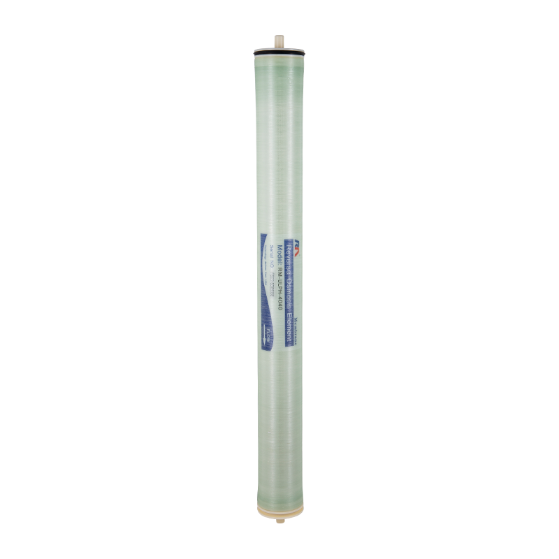
| 4040 | 4.0" × 40" | 2,000–5,000 GPD | Commercial and light industrial systems |
When replacing a residential membrane, verify the format code before ordering — the 1812 and 2012 sizes look similar but are not interchangeable. If your system housing accepts a 2012 membrane, upgrading from a 50 GPD to a 100 GPD membrane in the same housing is often possible and provides faster tank refill times. However, increasing the membrane flow rate also increases brine water consumption, so verify your drain line and system are rated for the higher brine flow before upgrading capacity.
Extending the working life of a reverse osmosis membrane is largely about consistent pre-filter maintenance and monitoring system performance over time. These practical habits keep the membrane operating at its rated efficiency and avoid the premature replacement costs caused by preventable damage.
